Hedge cutter project
click here for latest rebuild / upgrade picture page
The hedge is 300 meters long, 3 meters high, and 3 meters thick
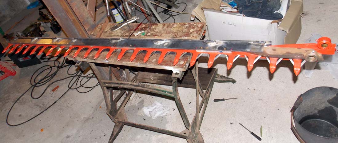
This blade is 1.8 meters long. I bought it new, and made the mild steel support box with aluminum slider blocks.
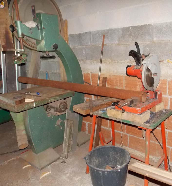
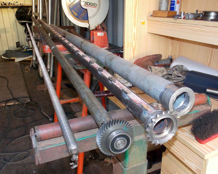
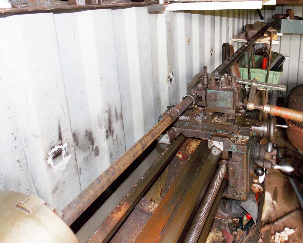
Here I'm cutting the main support tube. I bought the steel from a local scrap yard.
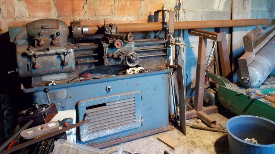
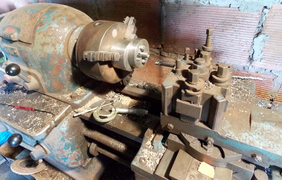
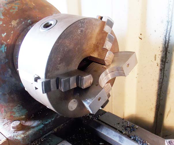
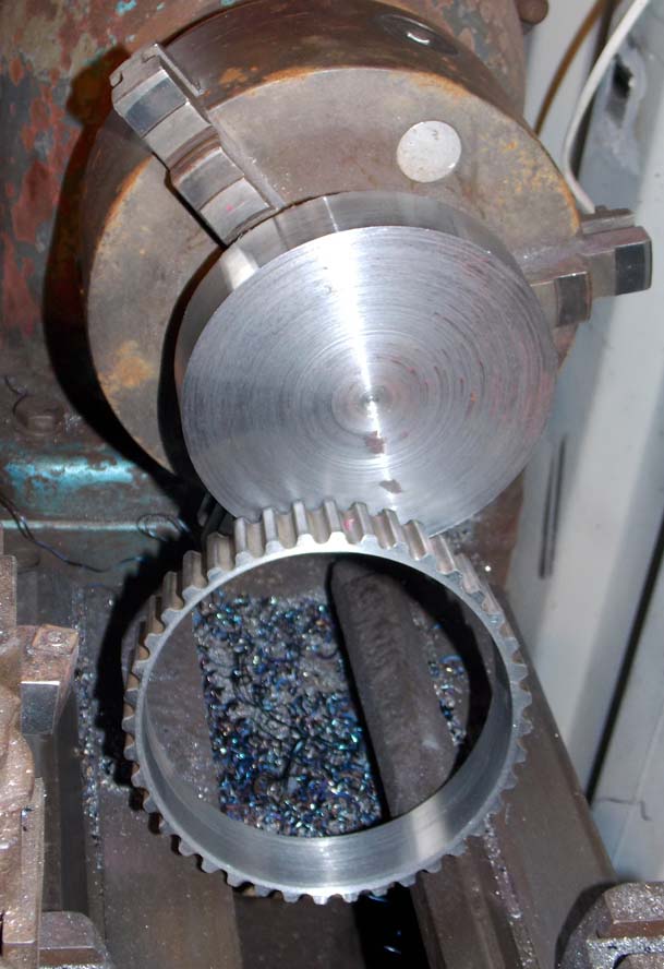
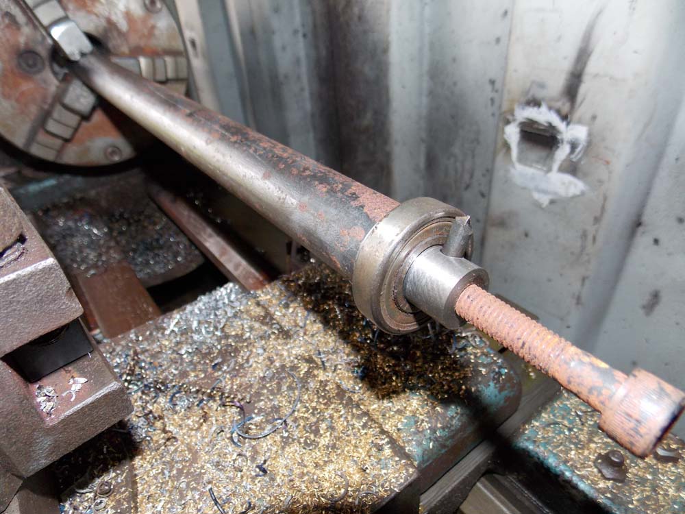
My little lathe can just about handle this; the extension tube is 90mm diameter and very thick wall, 2.5 meters long. just dressing one end to fit the swivel head.
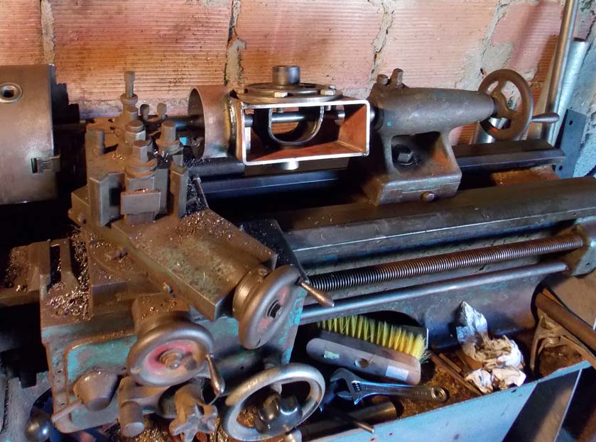
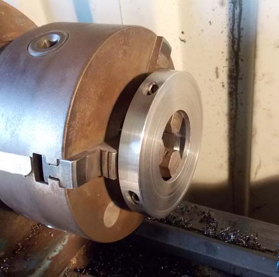
Cutting the inside of the swivel head collar to fit the extension tube. I wanted the rod in the center.
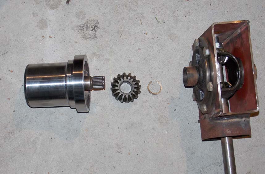
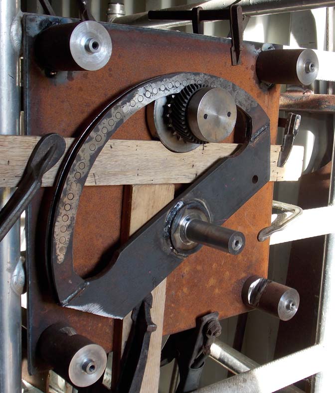
The swivel head with the rotating drum that will carry the blade, motor, and crankshaft. I'm going to add a collar to the swivel head that holds the drum instead of depending on the ring in the picture. One of the spider gears is free, the other is pinned to the shaft.
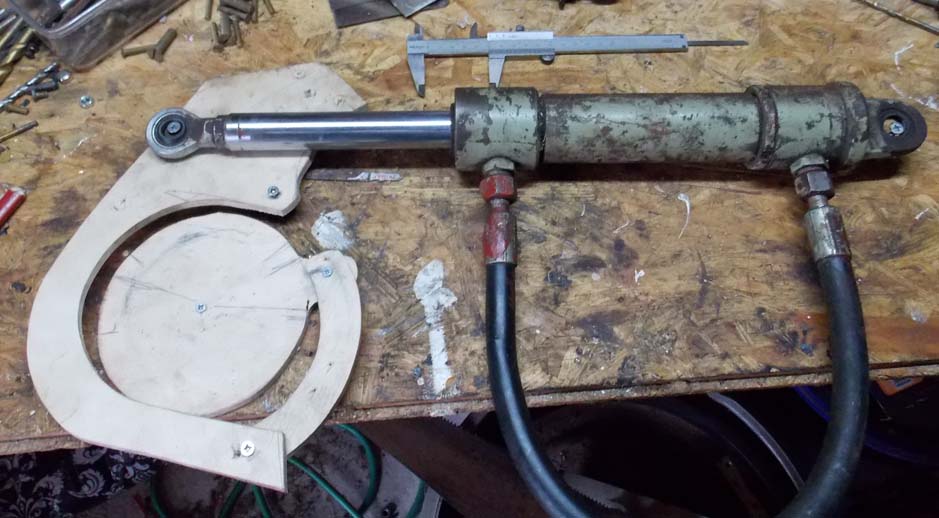
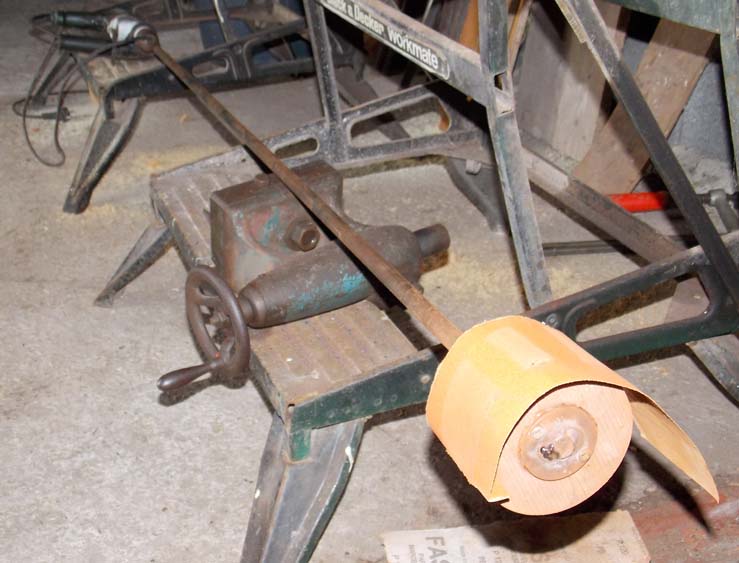
I need to rotate the 140mm outer tube by a full 180 degrees; this is a 1:1 wooden model with the actual hydraulic cylinder attached.

I couldn't find a piece of tube with the right dimensions, so I cut 2 pipes to fit together
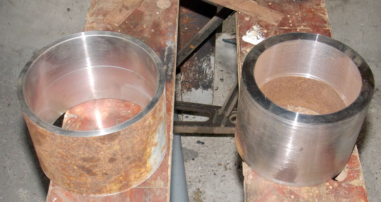
Here they are assembled, the sophisticated fitting implement is behind
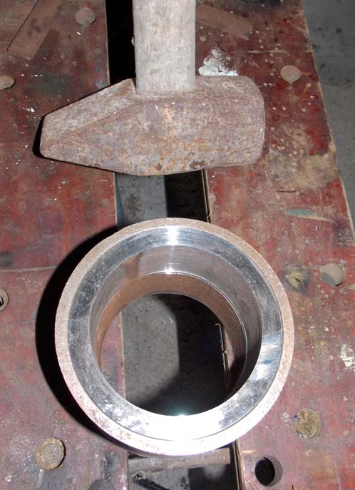
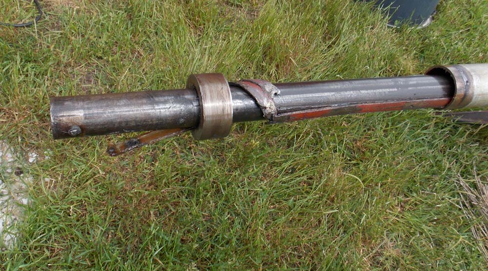
I've welded a ring onto the main tube and turned it on the lathe
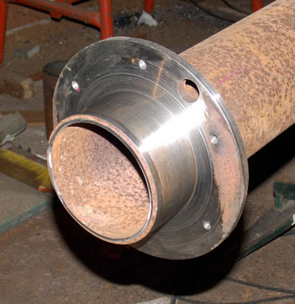
This collar [made from the pipes above] fits onto the end of the main tube above, and rotates freely. The retaining ring is made from flame cut plate.
More parts; most of this will become the crankshaft. the big ring will be cut into linkage parts. Yes, it was cut from the plate it's resting on.
The wooden linkage now made in steel. The collar will rotate the extension tube.
This is a tool I knocked up to clean the rust out of the inside of the main pipe.
I only have a 3-jaw chuck, so I'm using a block of steel to bolt the crankshaft sections to while boring. This is the end section, with the rough bearing support.
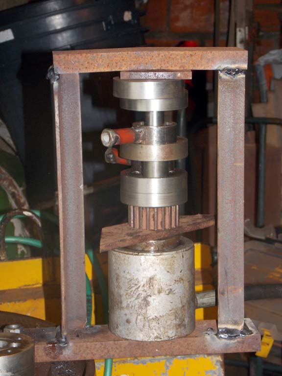
Pressing together the crankshaft. I bought the hydraulic ram and hand pump at a flea market long ago, I weld up a custom frame each time I use it.
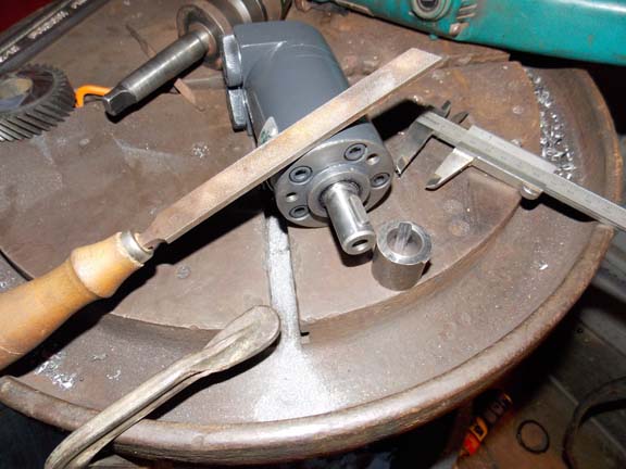
Final cut on the crankshaft, cutting the tail bearing rod at the back after assembly. The cogged pulley is a timing pulley from a junk car motor, and I've set the front bearing in the end of it.
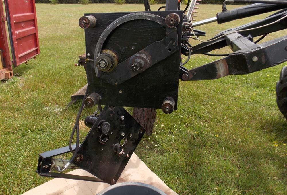
I've welded up and painted the cutting head; the blades, hydraulic motor, drive belt, crankshaft, all fit on there.
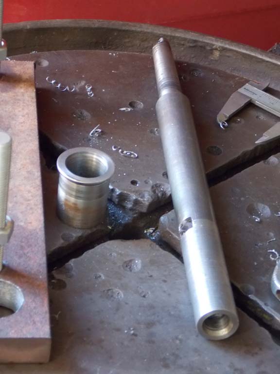
One of my little hydraulic cylinders was missing the eye at the end.
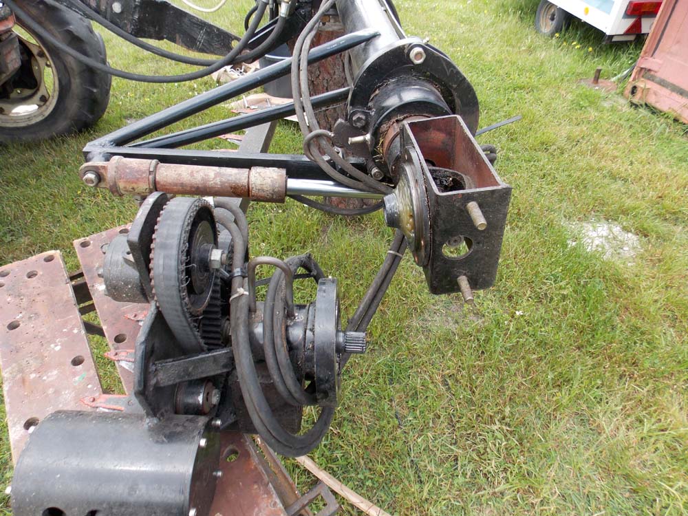
The gears are from an old car gearbox. I actually bought the sprocket new; the cog wheel is made from scratch, with 32 stainless steel rivets. I decided to use stainless because I had some 8mm rod left over from another job.
The cog wheel will be connected to one of the little hydraulic cylinders, and will rotate the sprocket 1.6 rotations. The sprocket will be attached to a 1-1/4" pipe [more on that later] which slides into a 2" pipe, which will rotate the cutting head.
Ok, the acme screw feeds into the 1" pipe with the gear and bearing on it. It will be fixed to the 2" pipe at one end. The 1" pipe will spin via a little hydraulic motor and the gears. The 1" pipe fits inside the 1-1/4" pipe with a bearing on each end, so it will pull on the screw and the 2" pipe to extend or retract the whole thing 2.2 meters [about 7 feet].
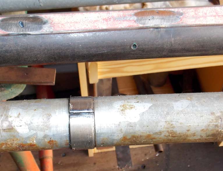
I added two of these bushings to the 1" pipe, to stop it from flopping around inside the 1-1/4" pipe. I managed to mount the pipe on my lathe and cut the grooves into it. the cut in the bushing slides up the weld that protrudes inside the larger tube. See the little hole in the larger pipe? that's for grease.
The 1-1/4" pipe has 2 strips of 1-1/2" pipe welded to the outside as splines.
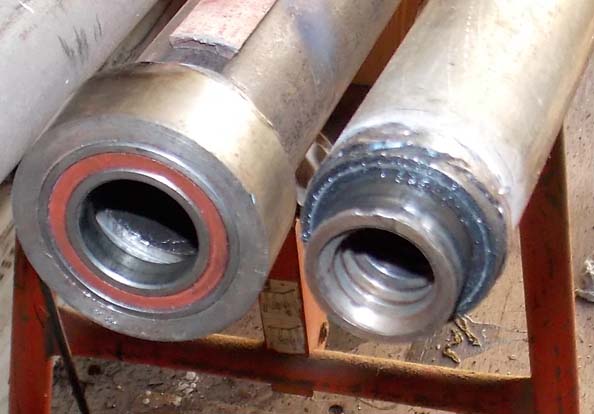
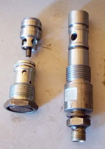
The tail end of the 1-1/4" pipe and the 1" pipe that fits inside it. The big collar slides inside the 2" pipe. the acme nut welded to the 1" pipe fits inside the bearing in the collar. The collar is lightly welded to the 1-1/4" pipe.
This is the retainer collar for the 1-1/4" tube. it will fit into a groove I cut into the sprocket. I cut the rough in half.
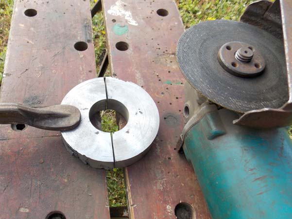
Milling the cut faces flat. I only have the one 3-jaw chuck.
Here I screwed the two halves back together and I'm making it round again. It fits into the sprocket groove nicely.
Poor man's method of cutting the keyway for the hydraulic motor gear that will drive the acme screw. I've pressed that collar into the gear now, but work has been stopped because the steel plate I bought at the scrapyard to mount all these parts on, turns out to be so hard I can't drill it with a cobalt bit.
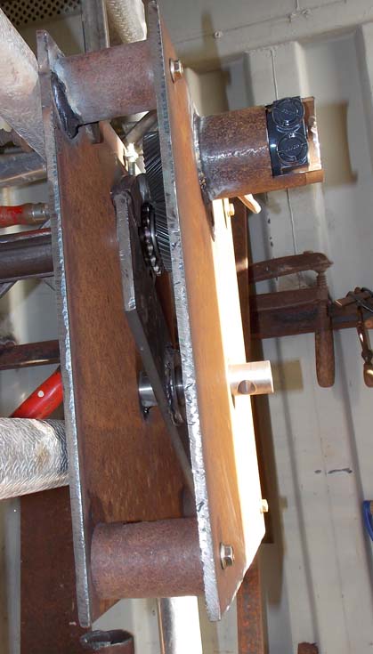
After swapping the hard plate for mild steel, I'm setting the split retainer onto the back plate; there's another equal plate that fits on top. the clamps and wood is holding the retainer in position while I drill, tap, and screw it down. The disk with 2 holes is a bearing holder that is now welded to the cover plate. The holes are for pushing the bearing out again.
This is the top plate; the end of the cog wheel shaft pokes through. The lever is fixed with the stainless tapered pin. the thread on the back of the pin makes it easy to remove. I used stainless because I wanted something a little tougher than the hole. Anyway, I couldn't find the mild steel rod I was looking but found a bit of stainless in my scrap box. The hole on the left is where I welded in the bearing cap above.
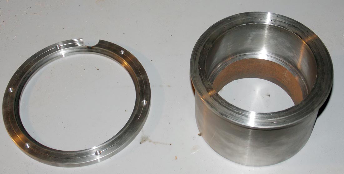
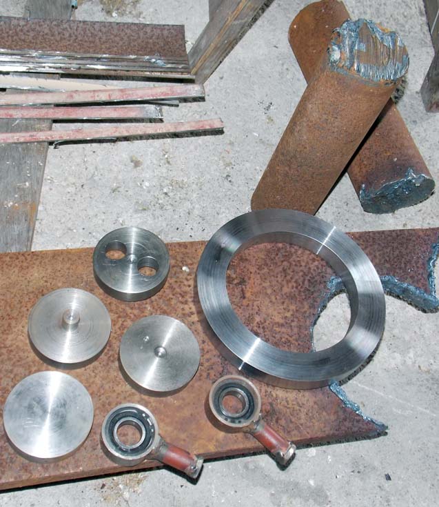
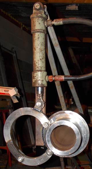
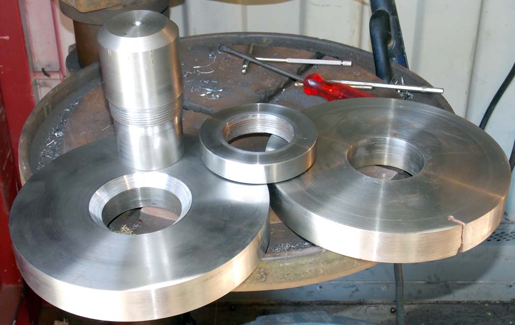
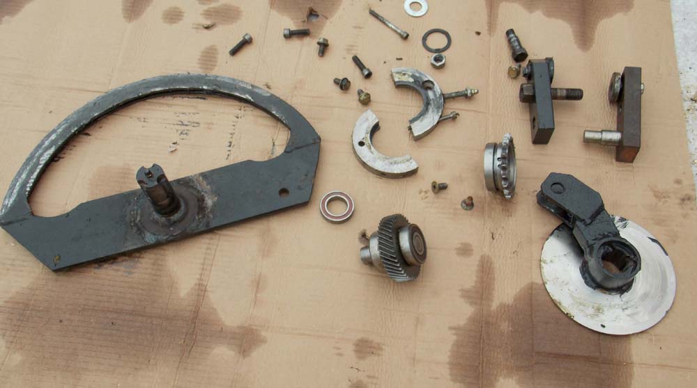
These are for the main pivot; the whole cutter will swing up and over to cut right or left. It sounds clever, but it was a stupid idea; this is what's made it all so complicated and long to build. The main tube will be welded to the ring on the left, the 75mm [3"] rod welded in the hole. The assembly will pivot on the ring in the right of the picture, held in by the ring nut. I designed this while starring at what was lying around at the local scrapyard. The rings are 240mm diameter and 40mm thick.
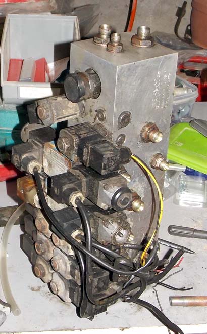
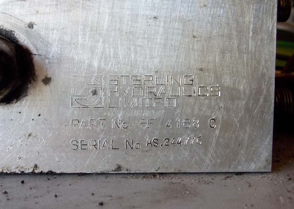
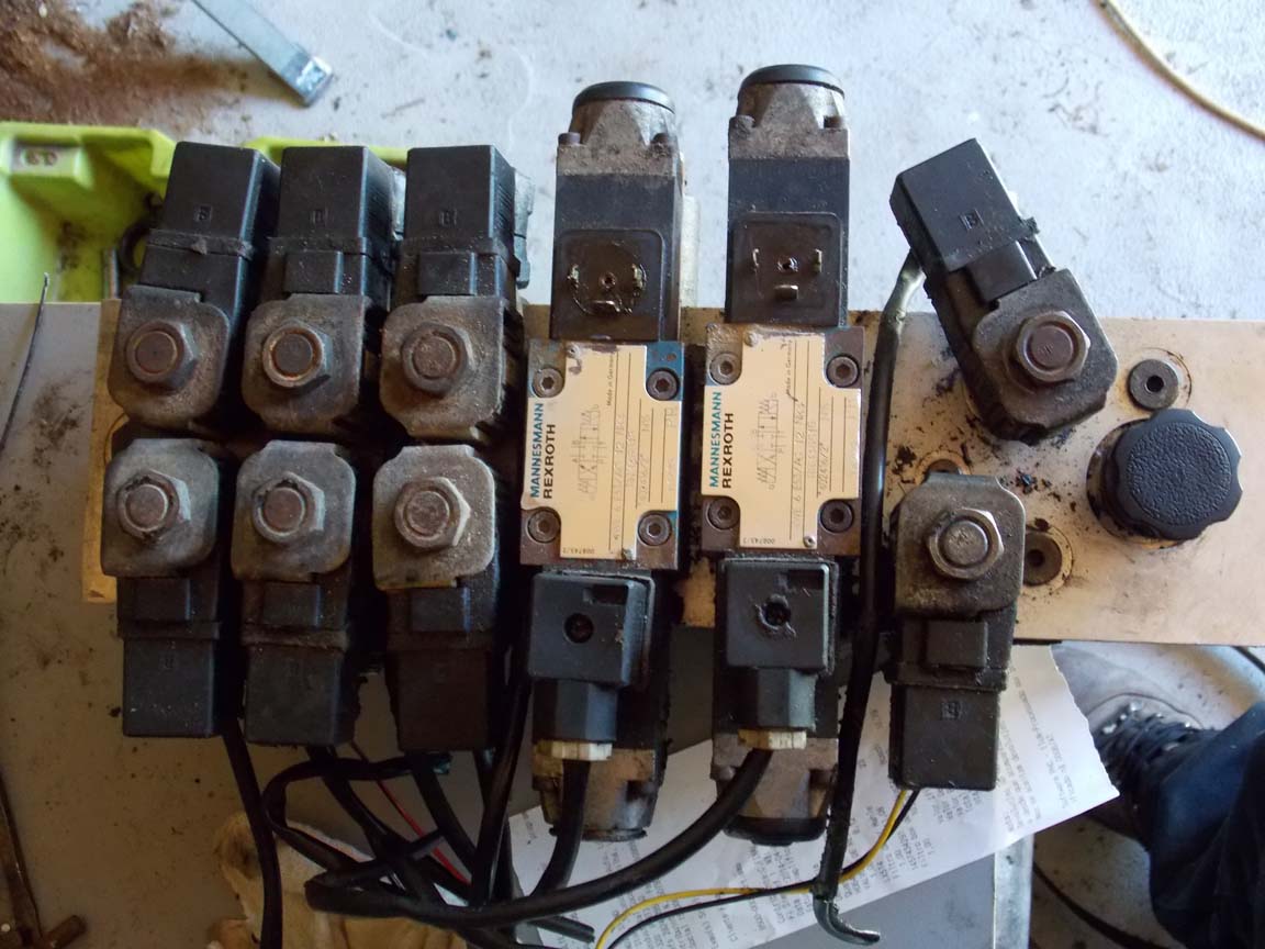
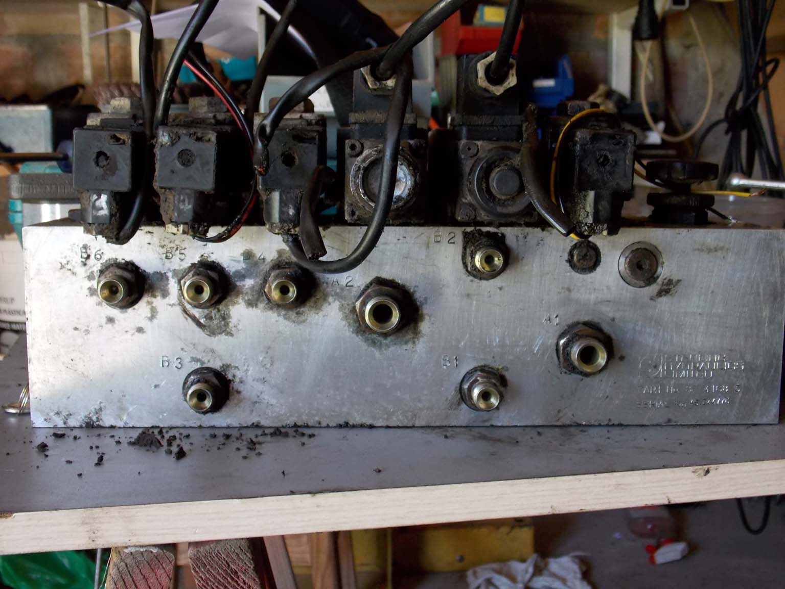
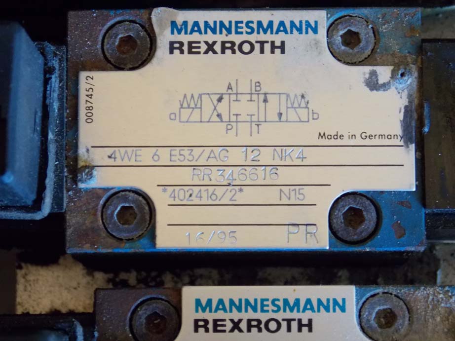
I posted the following pictures to "my tractor forum" for help with working out how the used [cheap, old] electro-hydraulic valve block works.
I figured it out in the end.
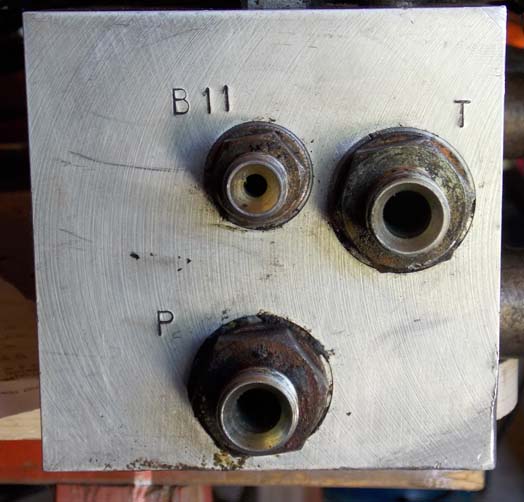
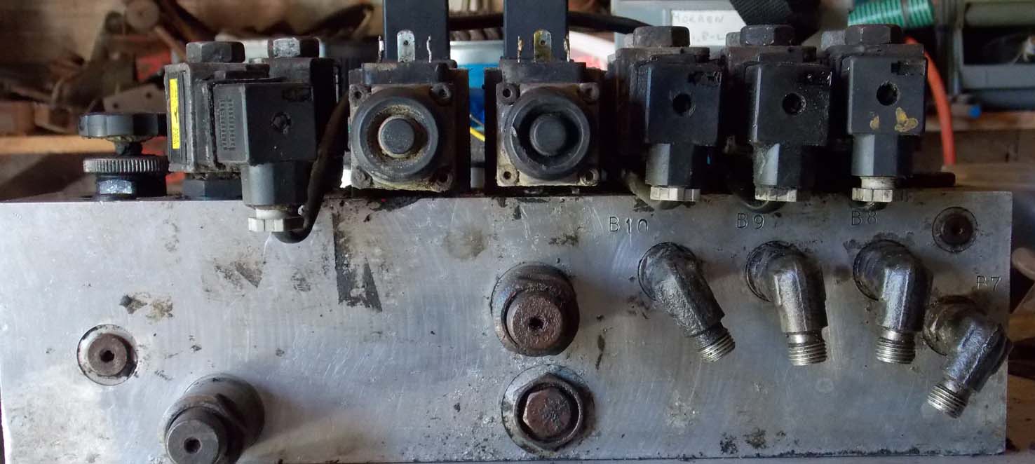
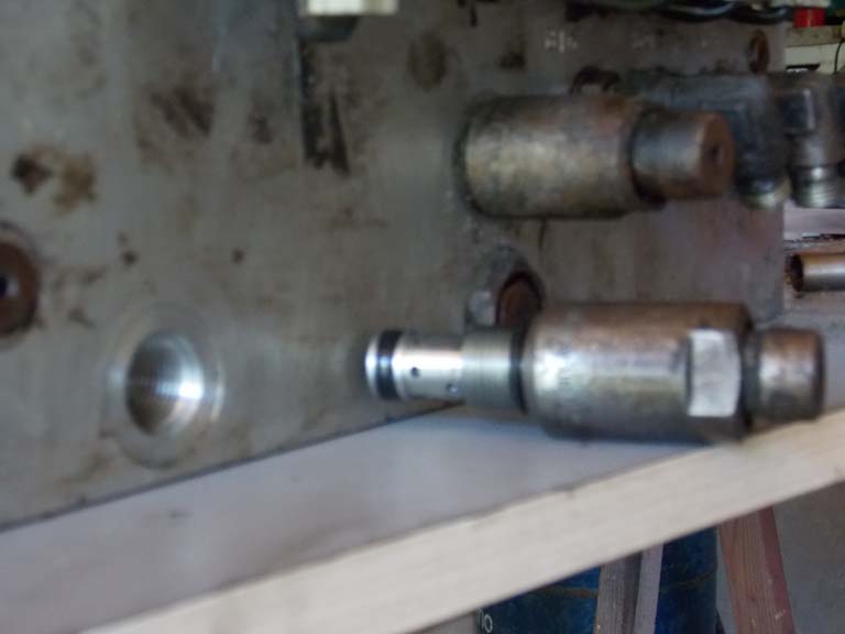
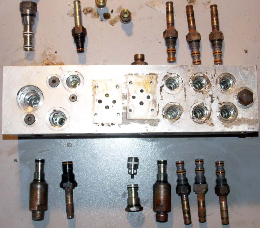
I removed the proportioning valve on the left and replaced it with my home made port on the right
Cogwheel box bolted together with the little hydraulic motor in a protective bit of scrap pipe.
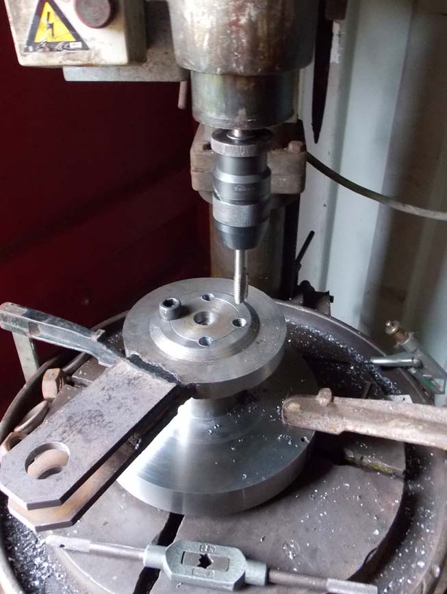
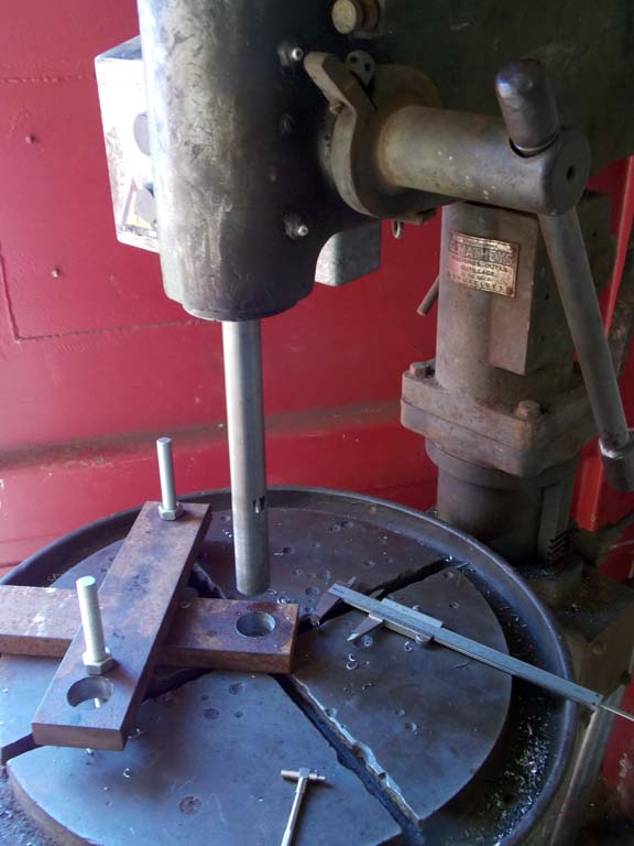
I use my drill press to tap the bolt holes straight. It's quick and accurate, but keep a finger on the stop button! the tap is 14mm [9/16"]. I bought it at a flea market 8 years ago...
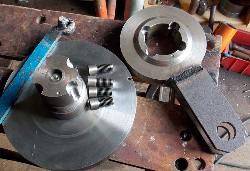
This is the pivot that will swing the whole machine from right to left; The lever will have a lot of torque, so these 4 14mm Allen screws are cut to fit snuggly into the 20mm countersink holes. two are slightly longer, they reach down to lock the screw ring below [not shown here].
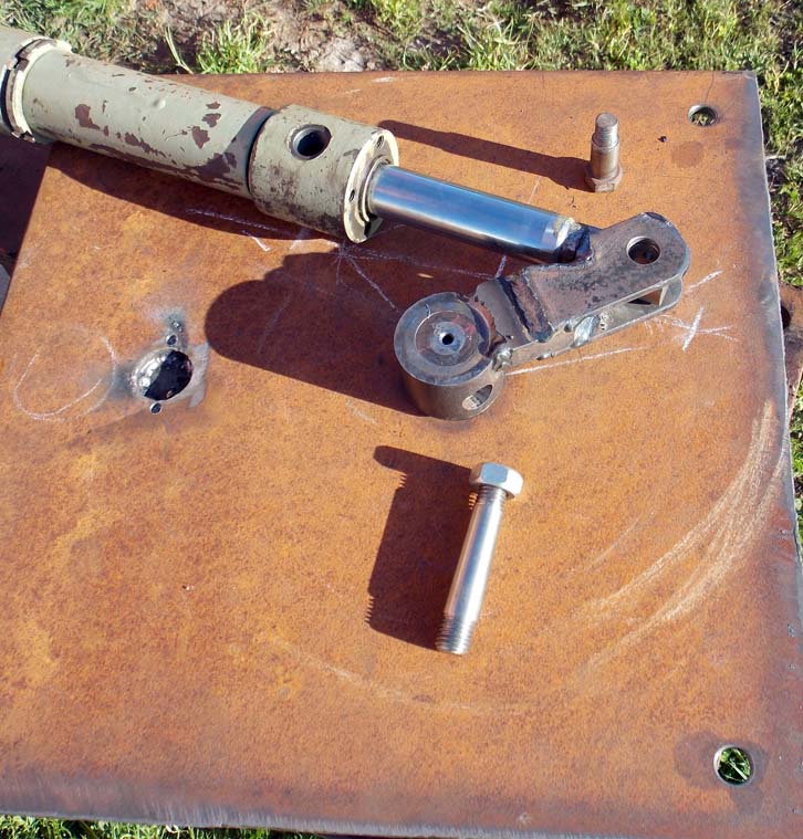
I had this big old cylinder lying around; too long for my project. My Portuguese neighbor told me "just cut it." So I did.
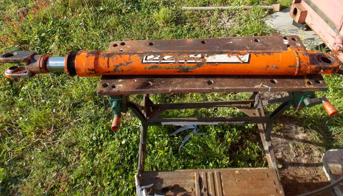
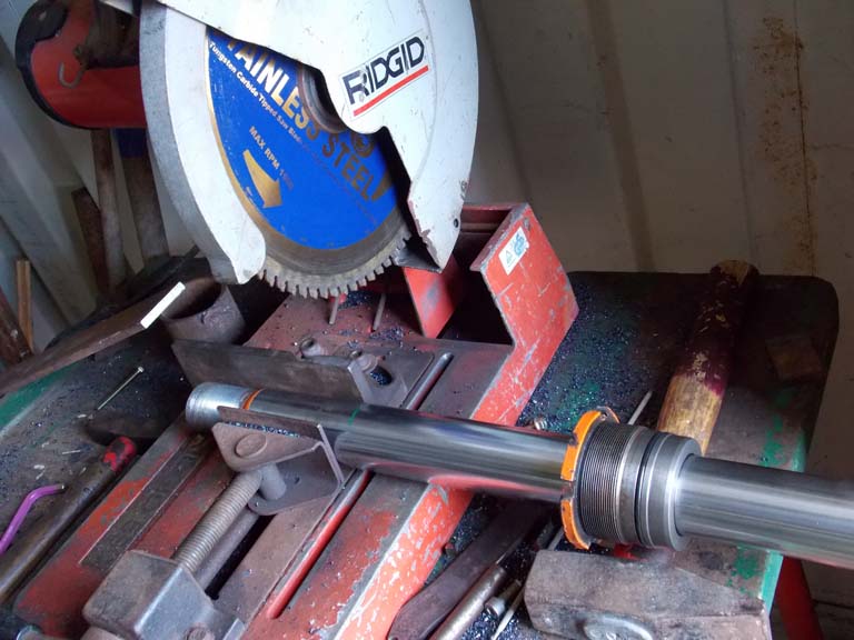
The rod was harder than I realized, and killed my cutting blade. I hate it when that happens.
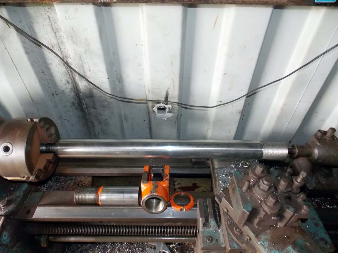
Threading the shortened hydraulic cylinder rod. I'm still new at this, so I was happy when it came out well.
I needed to bore some straight 30mm holes for the linkages, so I made this boring bar. It fits in the Morse 2 taper of my big drill press and is steadied at the bottom by the insert that fits into the base. It can also be used in the lathe between the chuck and center. the cutter is clamped by an Allen screw. I put a little ball bearing ball and a short piece of 6mm rod in there, so tightening the screw doesn't move the cutting bit.
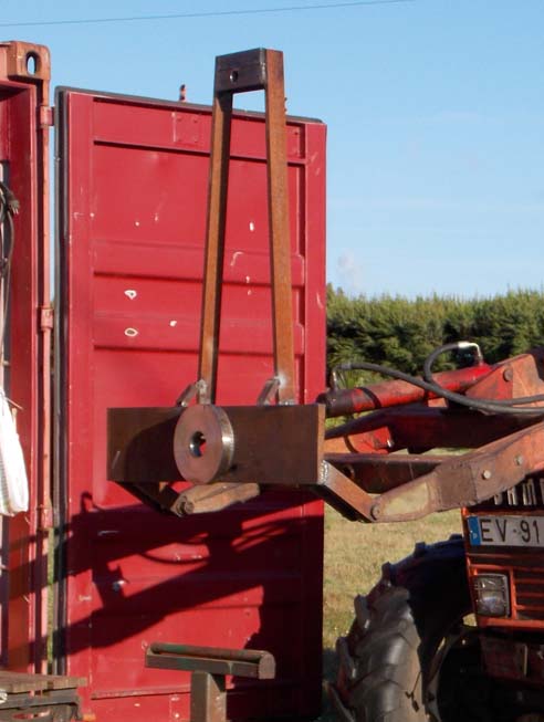
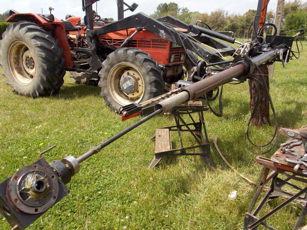
The frame is now mounted on the FEL. I'll assemble the hedge cutter with it on the tractor; I don't have anything else that can hold it in position while I work on it. The design was heavily influenced by what I found at the local scrapyard. The base plate is 22 [7/8"] thick but not quite wide enough. The bearing disk is 40mm thick, they had a big pile of rough blanks cut with a cnc plasma cutter. The sky is blue and my metal shop is in the container.
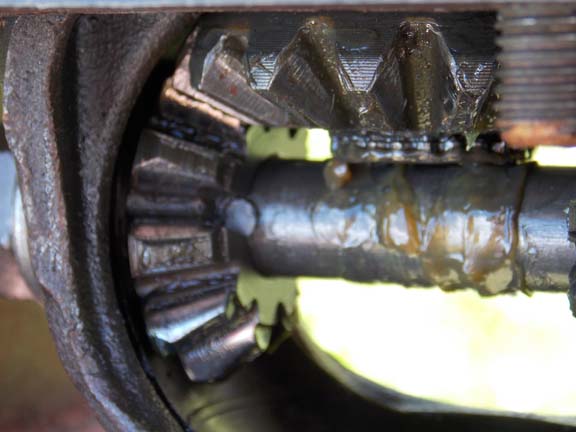
I knew that the 5mm pin fixing the gear to this shaft was the weak point in the design; but it broke off just from moving the machine into the garage for the night.
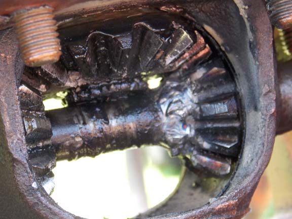
I didn't want to do this; but there seemed no other way. With the gear [I reversed and used the previously free one on the other side] welded, options for dismantling the machine for repairs are much more limited.
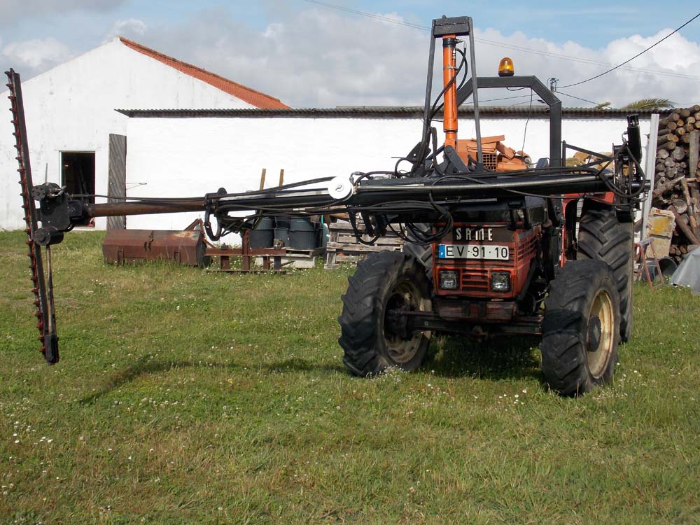
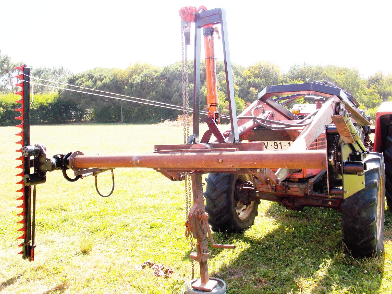
The machine so far; the mechanical parts are assembled, but I still need to run the hydraulics and electrics. It's pretty heavy. The chain hoist is to pull the tube upright to get in into the garage until the hydraulics are working.
after working for about 15 hours, the driving pulley broke. I torch cut a piece of leftover plate.
I don't have a cutting head big enough for this thick material.
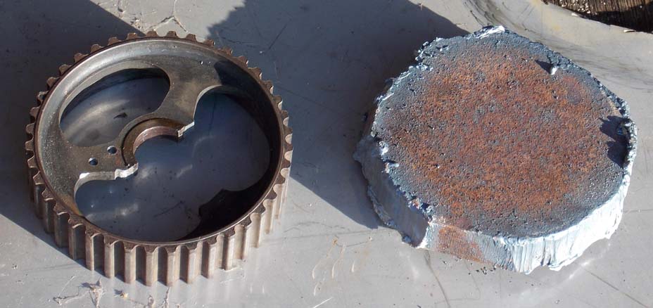
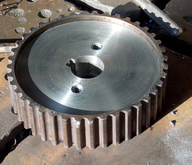
I heated he hoop to 260C in an oven, then slipped it over the new center. after cooling and shrinking, it seems quite tight.
The bolt holes are just in case I need to pull it off the shaft again someday.
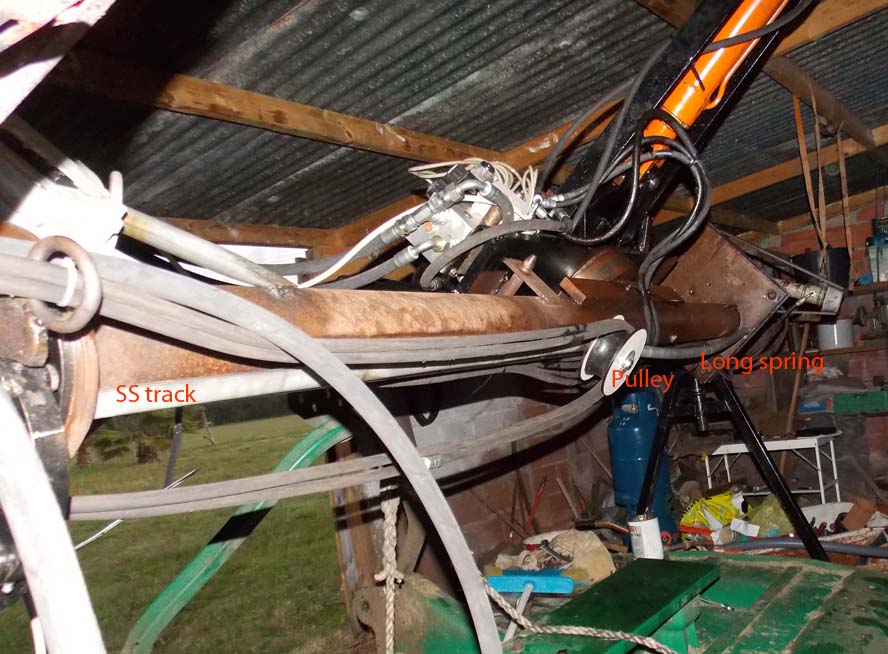
I finally made a hose guide so it won't be falling around. it was hard to source the big spring.
Woops; after drilling and reaming the hole for the SS tapered pin, there wasn't enough shaft left. Here I already cut it
from the cog wheel.
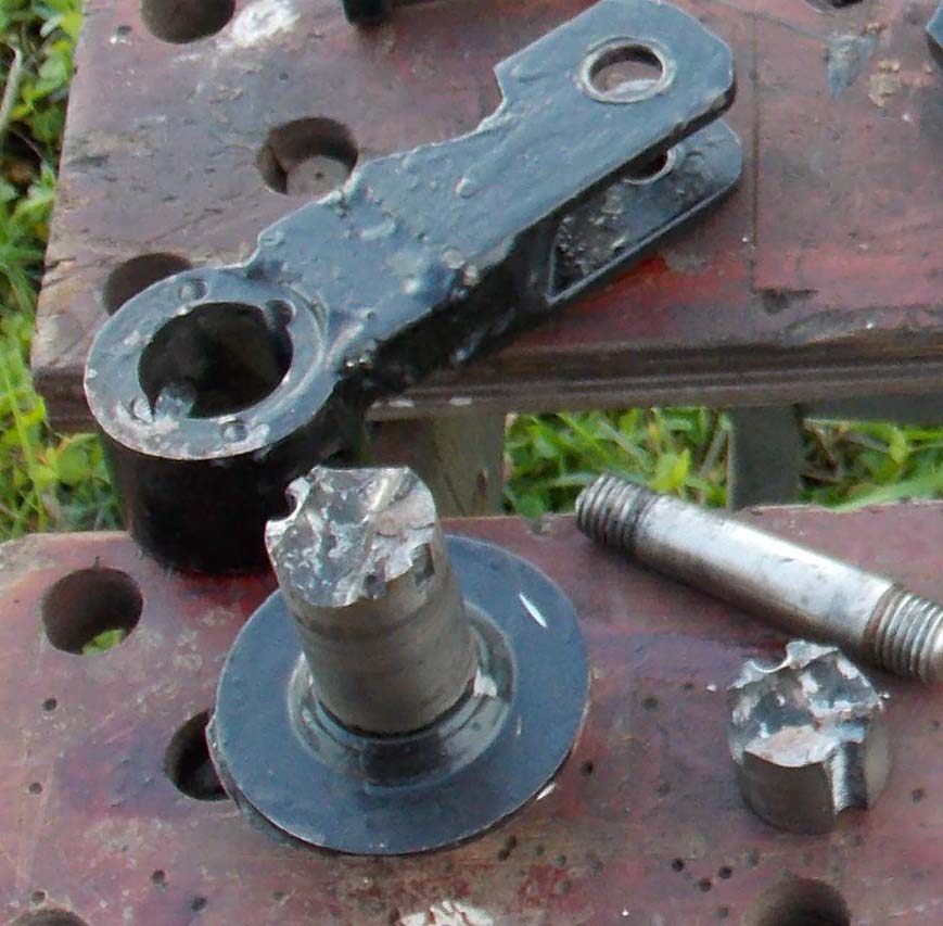
New shaft [30mm] made and welded on. the new lever and hub has a stainless disk on it, the blocks on the right
will be the caliper to hold the blade from rotating unless I apply force with its hydraulic cylinder.
The hydraulics weren't holding it steady.

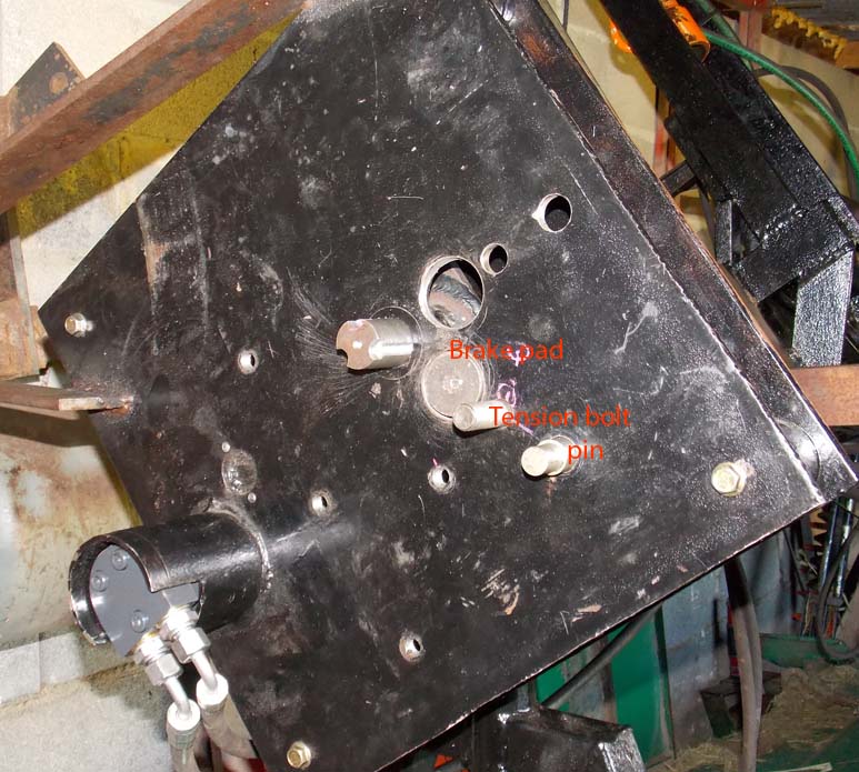
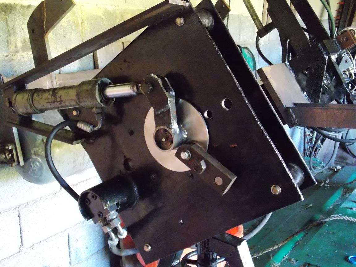
The end plate with new shaft, hub, lever, and brake. It works quite well.
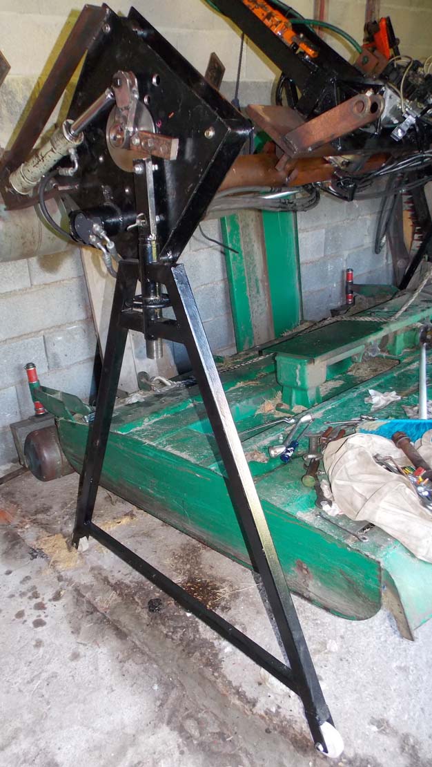
I made stands that hold it above my grass [+ brush] cutting deck in the shed. it has to be at an angle to fit under the low roof.
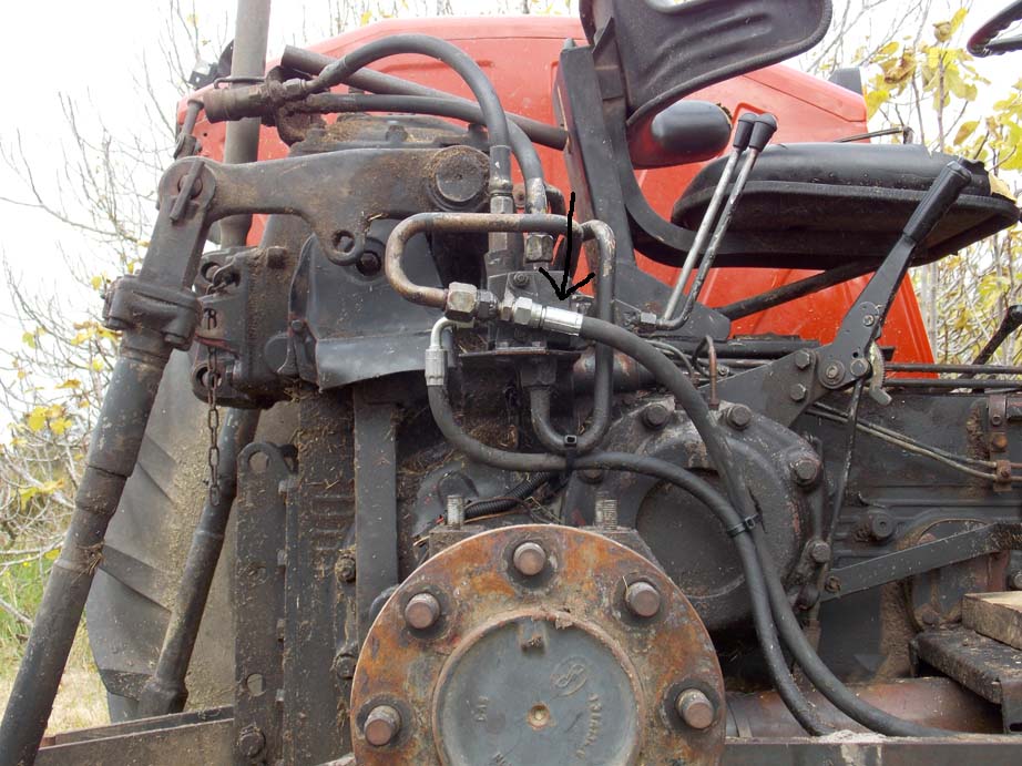
The oil pressure hose failed, spraying oil all over my dress work boots... I had to take off the wheel and fender to get at it.
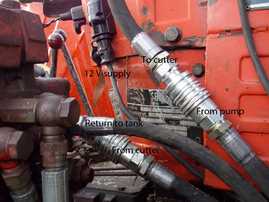
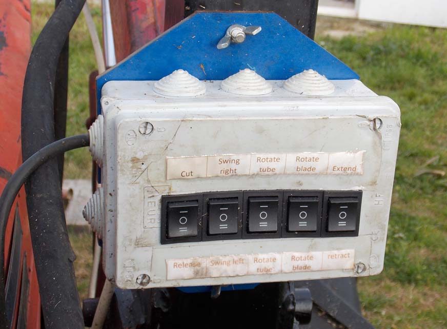
These quick connectors divert hydraulic oil through the hedge cutter's electric valve block when its mounted on the tractor.
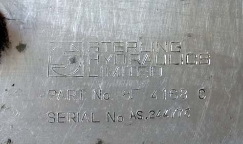
This valve block was used on a street sweeping machine for 20 - 30 years before I bought it on ebay. I had to modify it a little.
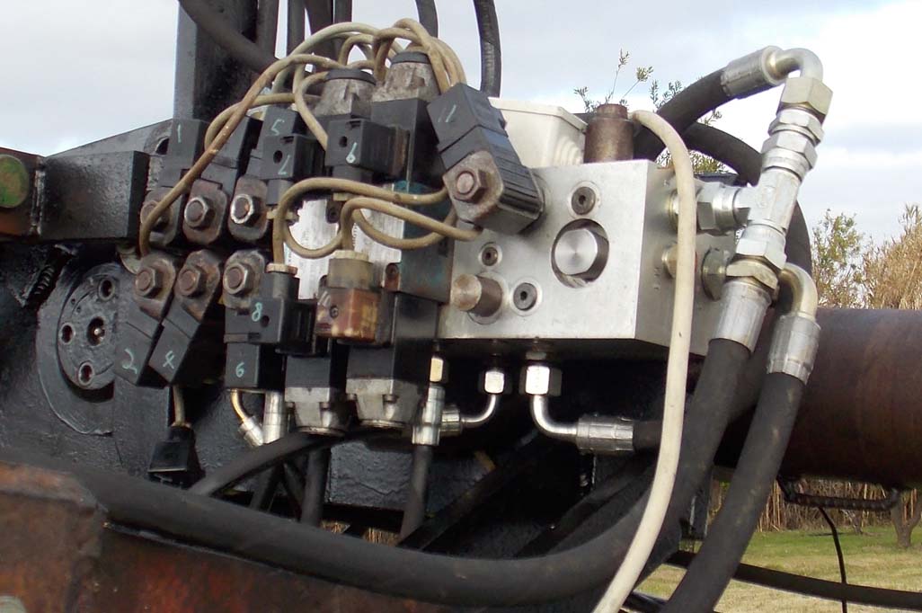
The cut switch stays on, the rest are momentary sprung switches. If the cutting blade gets stuck, I can reverse the motor by pressing 'release'
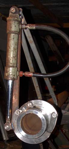
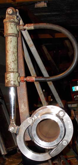
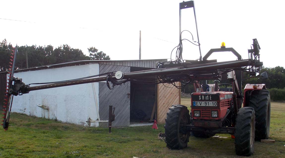
Jan 2015; in retracted position, with the big swingover cylinder removed for repair.
I can only use the machine on one side for now, but it's doing the job anyway. When it's fixed and put back, I'll make the promised video.
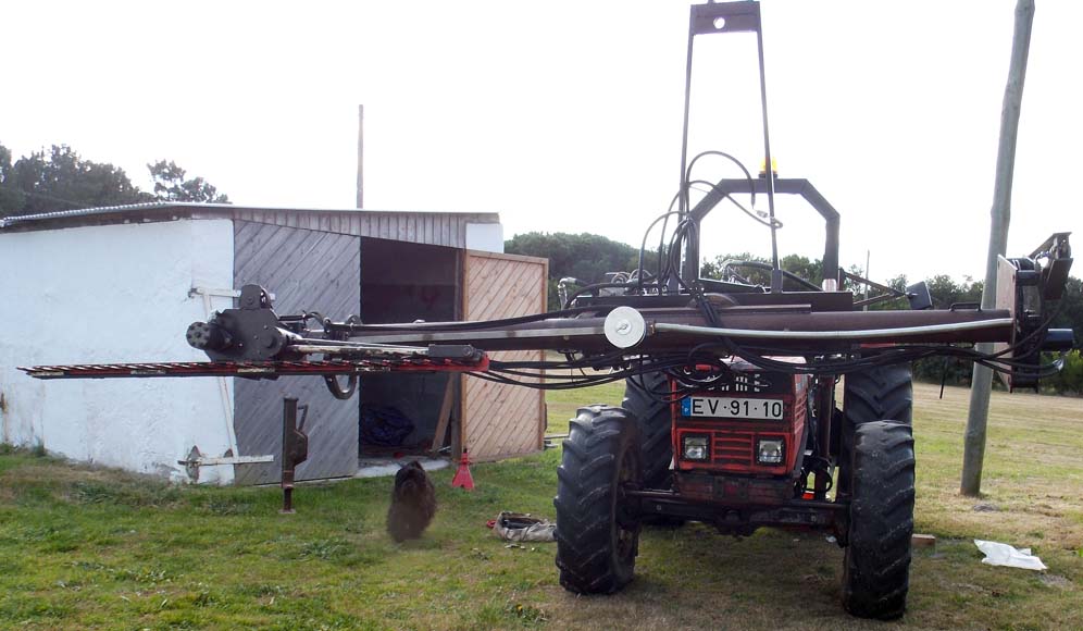
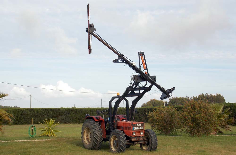
Here it's extended all the way out. yes, the loader arms twist a lot. I don't use it more than half way out unless there's no other way to reach the work.
The spring is stretched and the hose guide pulley is up near the end of the main tube.
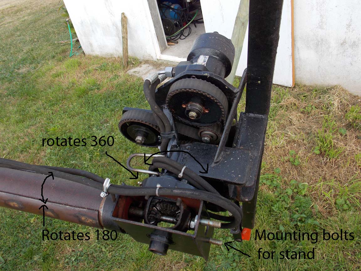
close-up of the cutter head. you can see the repaired drive pulley [painted black now] attached to the hydraulic motor.
The belt and pulleys are from a scrap Renault diesel motor I had. since I have the same motor in my car, I have a couple of old spare belts.
Update, May 2016;
The blade rotation stopped working; I had a hard time getting the machine apart, as the internal spline tube had the splines sheared and jammed.
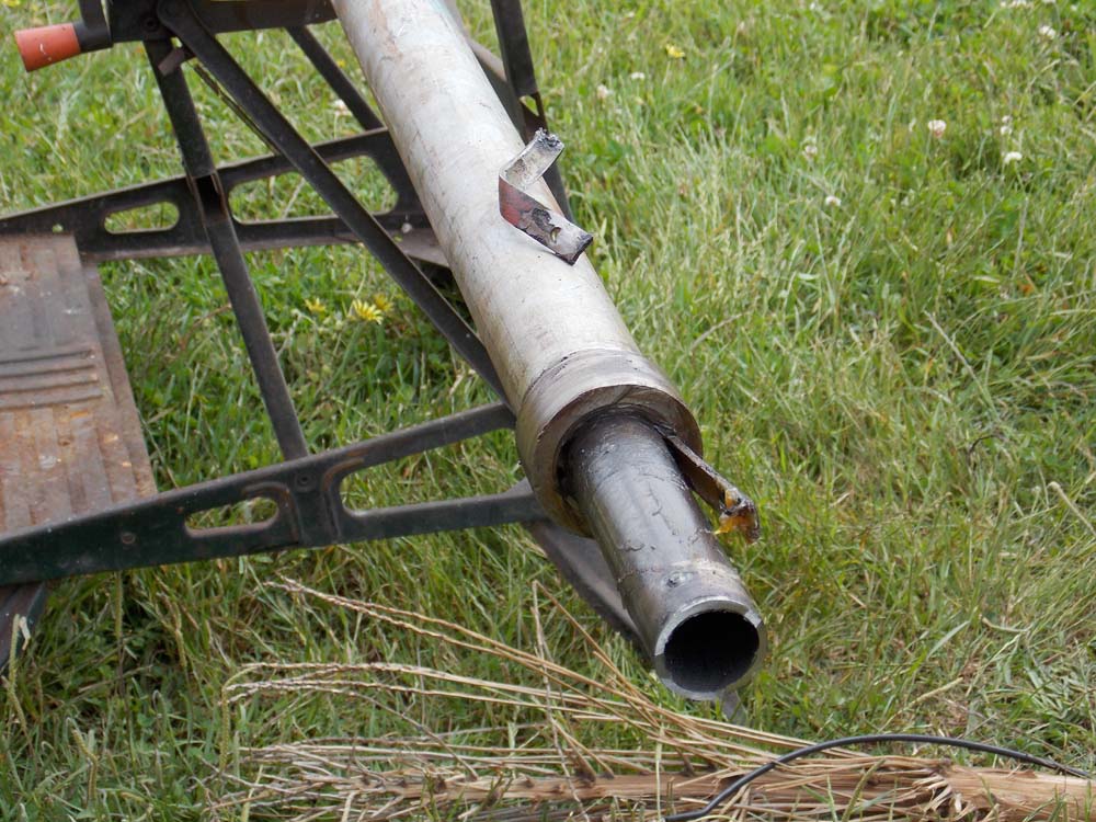
After repairing and drilling 50 holes to double the welds on the splines, I had some weld bumps inside the tube that blocked the spinning 1" pipe from fitting inside.
I made this rough boring tool;
It's a 25mm [1"] rod with a ball bearing and a drill shank cutting tool.
I clamped the work to the lathe tool holder and advanced it along the spinning tool; then backed it out, advanced the tool, and pulled the tube forward again to cut away the internal obstructions.
I wonder if I should write an instruction manual? Oh wait, this is it.
Reassembly;

And ready to work again!